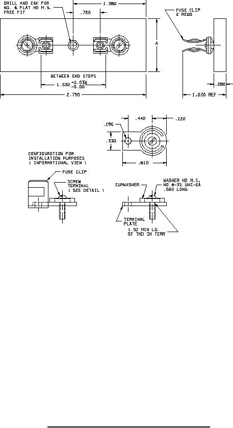
A-A-55518/4C
Inches
mm
Inches
mm
.030
0.76
.760
19.30
.060
1.52
.810
20.57
.196
4.98
1.030
26.16
.220
5.59
1.380
35.05
.280
7.11
1.520
38.60
.330
8.38
1.530
38.86
NOTES:
.440
11.18
2.750
69.85
1. Dimensions are in inches.
2. Unless otherwise specified, tolerance is ±.005 inch (0.13 mm).
3. The following notes apply to width A of the fuseholder blocks (see table I).
a. The longitudinal centerline of single pole and outer pairs of fuse clips of multiple pole fuseholder
blocks shall be located .39 inch (9.9 mm) from the edge of the block.
b. The distance between longitudinal centerlines of adjacent pairs of fuse clips shall be .91 inch
(23.1 mm).
c. A minimum of two mounting holes shall be provided on multiple pole fuseholder blocks. These
holes shall be one each centrally located between the fuse clips on the longitudinal centerline of
the outer pairs of fuse clips.
FIGURE 1. Configuration and dimensions (screw terminals).
2