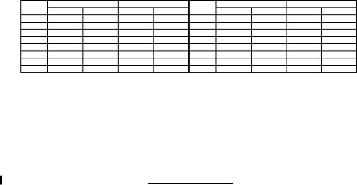
MIL-PRF-19207/12G
Ltr
Inches
mm
Ltr
Inches
mm
Min
Max
Min
Max
Min
Max
Min
Max
A
.175
.185
4.45
4.70
J
.845
.865
21.46
21.97
B
.651
.661
16.54
16.79
K
.290
.330
7.37
8.38
C
1.307
1.317
33.20
33.45
L
.030
.050
.76
1.27
D
1.180
1.22
29.97
30.99
M
---
2.610
---
66.29
E
1.760
1.800
44.70
45.72
N
.970
1.010
24.64
25.65
F
.980
1.020
24.89
25.91
P
.185
.195
4.70
4.95
G
.480
.520
12.19
13.21
R
1.307
1.317
33.20
33.45
H
.110
.120
2.79
3.05
S
.870
.910
22.10
23.11
NOTES:
1. All dimensions are in inches.
2. Metric equivalents ( to nearest 0.01 mm) are given for general information only.
3. Unless otherwise specified, tolerances are ±.02 (0.5 mm) for two place decimals and ±.005 (0.13
mm) for three place decimals.
4. Mounting hardware and gasket supplied loose in plastic bag.
5. The shape of the above fuseholder and knob marking are shown for information only. Slight
deviations from this outline drawing and/or the knob marking, which do not alter the functional
aspect of the device, are acceptable.
FIGURE 1. Type FHL22W fuseholder - contined.
REQUIREMENTS:
Interface and physical dimensions: See figure 1.
Cap and body molding material: It is recommended that types MAI-60, GDI-30F or SDG-F of
American Society for Testing and Materials ASTM-D5948 be considered for meeting the body molding
material requirements of this specification. ASTM-D3935 is also suggested as guidance for cap
material.
Fuse accommodations:
Ferrule type:
Size: 0.406 inch diameter, 1.500 inch length.
Style: F10: MIL-PRF-15160/10.
(or equivalent size and style).
Poles: One.
Rating: 15 amperes, 250 volts maximum.
30 amperes, 125 volts maximum.
Panel thickness: 0.187 inch maximum.
Indicating: Fuseholder shall be such that the fuse red button pop-up is clearly visible through the
transparent cap, when the fuse has blown, under 22 to 28 foot-candles of light.
Lamp series resistor: None.
2
For Parts Inquires call Parts Hangar, Inc (727) 493-0744
© Copyright 2015 Integrated Publishing, Inc.
A Service Disabled Veteran Owned Small Business