MIL-PRF-19207/18K
Ltr
Inches
mm
Ltr
Inches
mm
Min
Max
Min
Max
Min
Max
Min
Max
A
.695
.715
17.65
18.16
M
.302
.332
7.67
8.43
B
.670
.690
17.02
17.53
N
.302
.332
7.67
8.43
C
.555
.575
14.10
14.61
P
.545
.565
13.84
14.35
D
.038
.044
.965
1.12
R
.155
.175
3.94
4.45
E
.098 (REF)
2.49 (REF)
S
2.780
2.840
70.61
72.14
F
.125
.135
3.18
3.43
T
.145
.175
3.68
4.45
G
1.000
1.030
25.40
26.16
U
.630
.650
16.00
16.51
H
---
1.650
---
41.91
V
.410
.430
10.41
10.92
J
---
.085
---
2.16
W
---
.120
---
3.05
K
1.292
1.332
32.82
33.83
X
.335
.345
8.51
8.76
L
---
.375
---
9.53
Y
.400
.420
10.16
10.67
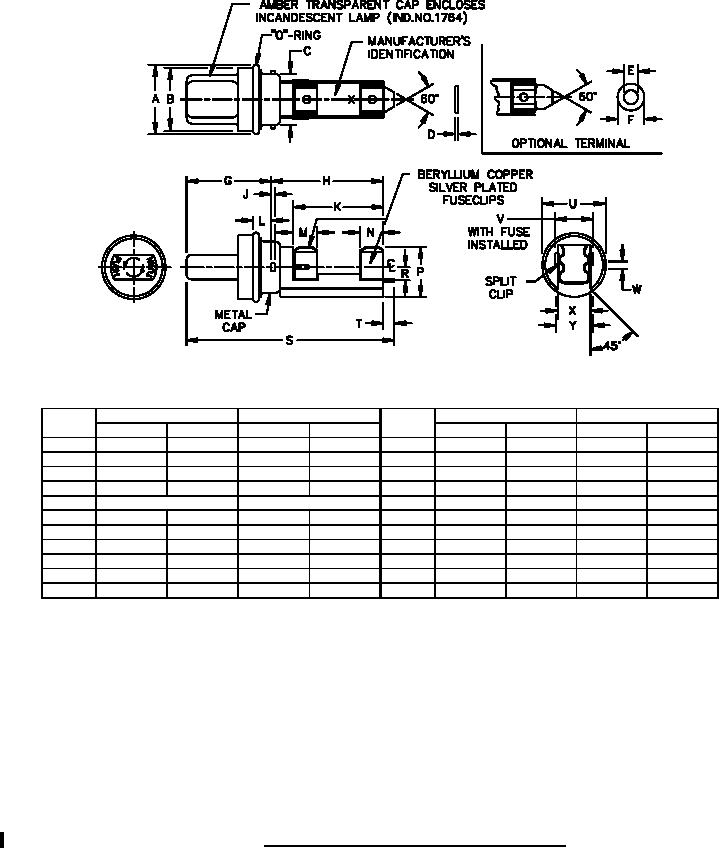
NOTES:
1. Dimensions are in inches. Metric equivalents are for general information only, based upon 1 inch = 25.4 mm.
2. Unless otherwise specified, tolerances are ±.02 (0.51 mm) for two place decimals and ±.005 (0.13 mm) for
three place decimals.
3. Cap and body molding material: It is suggested that type MAI-60, GDI-30F or SDG-F of American Society for
Testing and Materials ASTM-D5948 be considered for meeting the cap and body molding material
requirements of this specification. ASTM-D3935 is also suggested as guidance for cap material.
4. All of the type FHL29G fuseholders submitted for delivery shall have been subjected to the dripproof test in
accordance with 4.6.16.2 of MIL-PRF-19207.
5. Mounting hardware:
Screw: 6-32UNC-2A, .875 inch (22.23 mm) long (minimum).
Pan/round head with sealing washer or pan self-sealing.
Nut:
6-32 UNC-2B square. A threaded metal insert may be used in lieu of nut.
FIGURE 3. Fuse carrier for FHL29G and FHL30G fuseholders.
3
For Parts Inquires call Parts Hangar, Inc (727) 493-0744
© Copyright 2015 Integrated Publishing, Inc.
A Service Disabled Veteran Owned Small Business