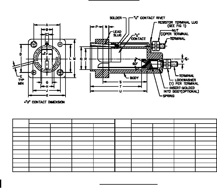
MIL-PRF-19207/19N
NOTES:
1. Dimensions are in inches. Metric equivalents are given for general information only.
2. Unless otherwise specified, tolerances are .XX ± 0.02 and .XXX ± 0.005.
3. All of the type FHL30G fuseholders submitted for delivery shall have been subjected to the drip-
proof test in accordance with MIL-PRF-19207, 4.6.16.2.
4. Mounting hardware: Screws, sealing, panhead, slotted, stainless steel or zinc plated steel, 6-
32UNC-2A x 1.125 inches (28.58 mm) long (min) or 6-32UNC-2A x 1.125 inches (28.58 mm) long
(min) with sealing washer, 2 each. Mounting hardware and gasket may be provided loose in a
plastic bag or installed on the fuseholder
5. Body material: It is recommended that type MAI-60 or GDI-30F of American Society For Testing
and Materials (ASTM) ASTM D5948 be considered for meeting the body molding material
requirements of this specification.
6. Marking: In addition to other required marking, the manufacturer's identification, the type
designation with an appropriate dash number and the voltage rating from table I shall appear on the
fuseholder body but the location of each is optional.
FIGURE 1. Type FHL30G fuseholder - Continued.
Ltr
Inches
mm
Ltr
Inches
mm
Min
Max
Min
Max
Min
Max
Min
Max
A
.745
.755
18.92
19.18
L
.945
.955
24.00
24.26
B
.435
.445
11.05
11.30
M
1.190
1.210
30.23
30.73
C
.188
.198
4.77
5.03
N
.140
.160
3.56
4.06
D
.870
.880
22.10
22.35
P
.385
.425
9.78
10.80
E
.125
---
3.17
---
Q
.695
.705
17.65
17.91
F
.385
.395
9.78
10.03
R
.575
.595
14.61
15.11
G
.360
.370
9.14
9.40
S
1.675
---
42.54
---
H
.435
.445
11.05
11.30
T
1.950
2.050
49.53
52.07
J
.845
.865
21.46
21.97
U
2.105
2.155
53.47
54.74
K
1.065
1.075
27.05
27.31
V
.140
.190
3.56
4.83
FIGURE 2. Body for FHL30G fuseholder.
2
For Parts Inquires call Parts Hangar, Inc (727) 493-0744
© Copyright 2015 Integrated Publishing, Inc.
A Service Disabled Veteran Owned Small Business