MIL-DTL-24646/17B
REQUIREMENTS
Symbol numbers: See table I.
Design:
Electrical rating: 500 volts alternating current, 0-30 ampere, 60 hertz.
Dimensions and configuration: See figures 1, 2, 3 and 4.
Wiring diagrams: See figure 5.
Mounting dimensions: See figure 3.
Degree of enclosure: Submersible (15 feet).
Designation and marking: See MIL-DTL-24646.
Fuse puller assembly: The fuse puller assembly shall have blades that engage the jaws fastened to
the base. The blades shall spread the jaws. The jaws shall grip the blade
with enough force to prevent heating when under full load.
Parts: The parts listed in table II and specified in MIL-DTL-24646 shall be used in the construction
of the fuse boxes specified herein.
General information:
Military part numbers and general information are as specified in table I.
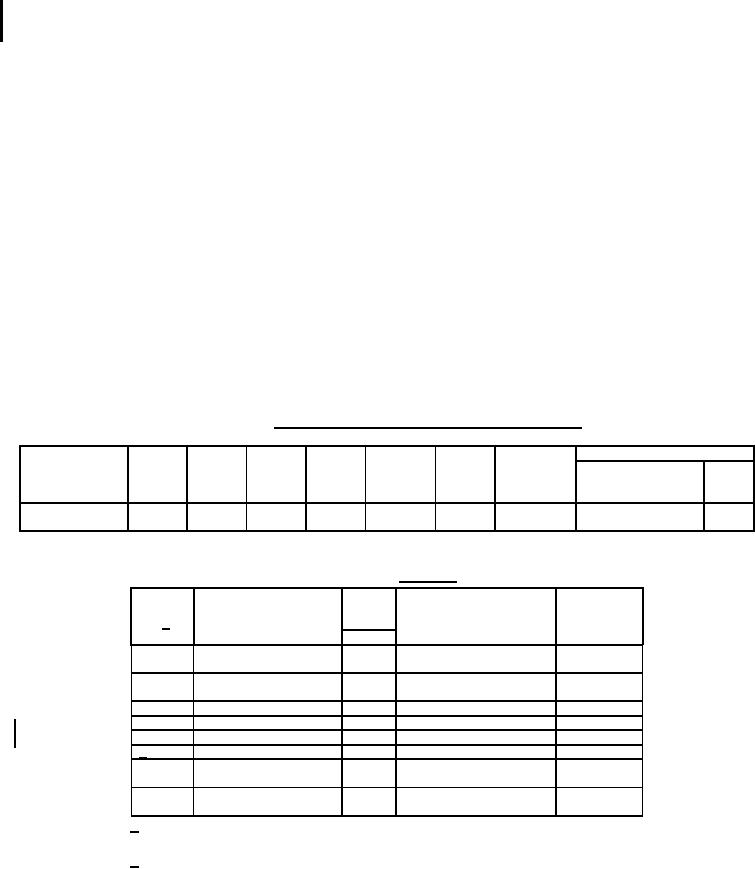
TABLE I. Military part numbers and general information.
Supersedes
Weight
Symbol
Military
No. of
Feeder
Branch
Fuse
Bus bar
in
no.
part no.
circuits
MCM
MCM
size
size
Drawing
Type
pounds
no.
M24646/17-
693.1
29.0
1
75
14
0-30A
0.62 x 0.19
9000-S-6202-74191
-
001
TABLE II. Parts list.
Remarks
Description
Item
QTY M
Material/specification
no. 1/
/-
001
01
Fuse box assembly
-
MIL-DTL-24646/17
See fig. 1
(sym 693.1)
02
Enclosure
1
M24142/6-004
See fig. 2
(10 x 13 x 5)
03
Fuse block assembly
1
MIL-DTL-24646/17
See fig. 4
04
Wiring diagram
1
See fig. 5
05
Fuse clip (0-30A)
6
A-A-55507/1-06
N/A
2/ 06
Fuse puller assembly
1
----
See fig. 6
N/A
07
Identification plate
1
Brass, ASTM B36/B36M
N/A
08
Information plate
1
Brass, ASTM B36/B36M
1/ Item numbers after the figure titles are the same as the item
numbers shown in this table.
2/ Warning shall be engraved on front of plate and filled with red enamel.
7
For Parts Inquires call Parts Hangar, Inc (727) 493-0744
© Copyright 2015 Integrated Publishing, Inc.
A Service Disabled Veteran Owned Small Business