MIL-DTL-9129G
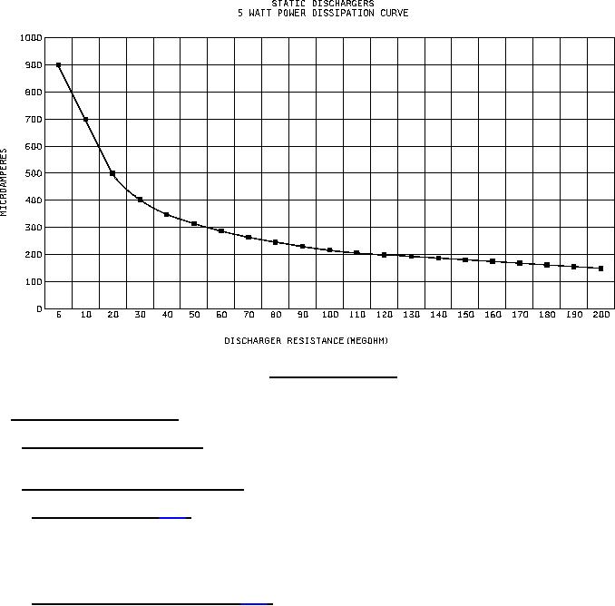
FIGURE 2. Power Dissipation test.
4.6 Methods of inspection and test.
4.6.1 Visual and mechanical inspection. Dischargers shall be inspected to verify that the physical dimensions,
materials, design, construction, marking, and workmanship are in accordance with the applicable requirements.
4.6.2 Discharge current measurement and test.
4.6.2.1 Discharge current (see 3.6.1). Discharge current, voltage and spacing between the discharge points shall
be measured, and recorded using the test configuration outlined in figure 1. Any leakage current in the test circuit
with the discharger removed shall be subtracted from the specified test current when increasing the test voltage to
the specified maximum. Ambient relative humidity and temperature shall be within the ranges of 40 to 60 percent and
16°C to 27°C, respectively.
4.6.2.2 Radio frequency discharge noise (see 3.6.2). Radio frequency discharge noise shall be measured using
the test configuration outlined in figure 3. The tester shall be in accordance with Air Force Drawing 7136810 or
equivalent tester assembly. The rms voltmeter shall be a "J" Fluke Model 910A, Hewlett Packard Model 3400A, or
equivalent. The amplifier, Tektronix type 1121 or equivalent, shall have an input impedance in excess of 1 megohm
and a flat frequency response from 5 Hz to 17 MHz. The tester shall be calibrated using a 16 gauge solid metal wire
7 inches long with a radius of curvature on the discharge end equal to one half of the wire diameter. The rms noise
voltage generated with the wire discharging 50 µA will be measured and recorded as the calibration standard. This
calibration standard is being specified as being 10 dB below the noise similarly generated by a simulated trailing
edge. The discharger will then be installed and its rms noise voltage generated at 50 µA shall be recorded. The dB
noise difference between the simulated trailing edge and discharger shall meet the requirements of paragraph 3.6.2.
When testing the calibration standard on the discharger, the end of the standard or the discharge area (as applicable)
will break the plane of the cone in figure 3.
10
For Parts Inquires call Parts Hangar, Inc (727) 493-0744
© Copyright 2015 Integrated Publishing, Inc.
A Service Disabled Veteran Owned Small Business