MIL-DTL-9129G
Inches
mm
.125
3.18
.500
12.70
.750
19.05
2.00
50.9
3.25
82.6
NOTES:
1. Dimensions are in inches.
2. Metric equivalents are given for information only.
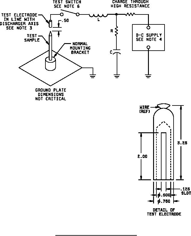
3. Test electrode to be supported at .50 (12.7 mm) in above tip of test
discharger.
4. Adjust voltage to allow 200 joules minimum of stored energy in `C'.
5. Voltage must cause flashover between test electrode and metal portion
of discharger.
6. Close test switch to allow approximately 2000 amperes ± 50% peak current.
7. Marx circuit may be employed to charge capacitors in parallel and to
discharge in series connection.
8. Unless otherwise specified, tolerances are ±.005 (0.13 mm) for three
place decimals and ±.02 (0.51 mm) for two place decimals.
FIGURE 5. Electrical impulse flashover test configuration.
14
For Parts Inquires call Parts Hangar, Inc (727) 493-0744
© Copyright 2015 Integrated Publishing, Inc.
A Service Disabled Veteran Owned Small Business