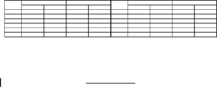
MIL-PRF-19207/13J
Ltr
Inches
mm
Ltr
Inches
mm
Min
Max
Min
Max
Min
Max
Min
Max
A
.175
.185
4.45
4.70
G
.845
.865
21.46
21.97
B
1.307
1.317
33.20
33.45
H
.860
.900
21.84
22.86
C
1.760
1.800
44.70
45.72
J
---
2.680
---
68.07
D
1.180
1.220
29.97
30.99
K
.870
.910
22.10
23.11
E
1.010
1.050
25.65
26.67
L
.185
.195
4.70
4.95
F
.110
.120
2.79
3.05
M
1.307
1.317
33.20
33.45
NOTES:
1. Dimensions are in inches.
2. Metric equivalents are given for general information only.
3. Unless otherwise specified, tolerances are ±.02 (0.5 mm) for two-place decimals and ±.005 (0.13 mm) for
three-place decimals.
4. Marking on fuseholder cap shall be raised lettering (3 places).
FIGURE 1. Type FHN23W fuseholder - continued.
REQUIREMENTS:
Interface and physical dimensions: See figure 1.
Cap and body molding material: Cap and body molding materials shall be selected to enable the fuseholder to
meet the performance requirements of this specification. Additional information and guidance on body molding
material are specified in the notes.
Fuse accommodation:
Ferrule type:
Size: 0.406 inch (10.31 mm) diameter, 1.500 inches (38.10 mm) length.
(or equivalent size and style)
Poles: One.
Rating: 30 amperes, 500 volts maximum.
Panel thickness: 0.187 inch (4.75 mm) maximum.
Lamp series resistor: None.
Terminals: Solder lug type.
Enclosure: Watertight.
Test fuses:
Temperature rise: F09A250V30A of MIL-PRF-15160/9.
Short circuit: F60C500V30A of MIL-PRF-15160/60.
Mechanical shock: Method II of MIL-PRF-19207.
Terminal strength: 5 pounds.
Torque:
Cap insert: 15 pounds-inch.
Salt spray (corrosion): Test condition B.
Endurance: 300 operations.
Mounting hardware:
2
For Parts Inquires call Parts Hangar, Inc (727) 493-0744
© Copyright 2015 Integrated Publishing, Inc.
A Service Disabled Veteran Owned Small Business