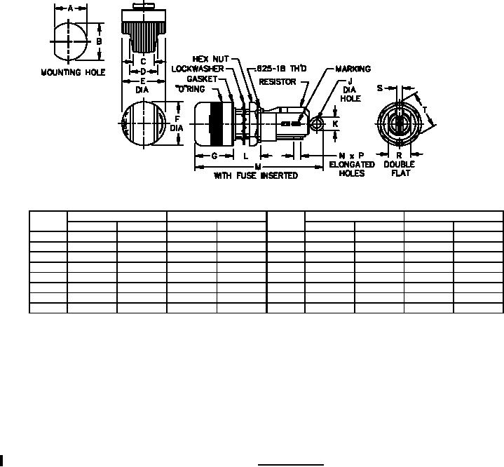
MIL-PRF-19207/8H
Ltr
Inches
mm
Ltr
Inches
mm
Min
Max
Min
Max
Min
Max
Min
Max
A
.570
.575
14.48
14.61
K
---
.280
---
7.11
B
.625
.635
15.88
16.13
L
.420
10.67
.460
11.68
C
.480
.520
12.19
13.21
M
---
.280
---
7.11
D
.280
.340
7.11
8.64
N
.070
.110
1.78
2.79
E
.920
.960
23.37
24.38
P
.100
.140
2.54
3.56
F
.930
.970
23.62
24.64
R
.510
.520
12.95
13.21
G
.820
.860
20.83
21.84
S
.035
.045
.88
1.14
J
.090
.130
2.29
3.30
T
.790
.830
20.07
21.08
NOTES:
1. Dimensions are in inches.
2. Metric equivalents are given for general information only.
3. Unless otherwise specified, tolerances are ± 0.02 (0.51 mm) for two place decimals and ±0.005 (0.13mm) for
three-place decimals.
4. Terminal is .20 inch wide with a .10 inch minimum diameter solder hole.
5. Cap and body molding material: It is suggested that type MAI-60, GDI-30F or SDG-F of American Society for
Testing and Materials ASTM-D5948 be considered for meeting the cap and body molding material
requirements of this specification. ASTM-D3935 is also suggested as guidance for cap material.
6. Gaskets: It is suggested that gaskets which meet class 3 of A-A-59588 be considered for use.
FIGURE 2. Type FHL17G2.
REQUIREMENTS:
Cap and body molding material: Cap and body molding materials shall be selected to enable the fuseholder to
meet the performance requirements of this specification. Additional information and guidance on body molding
material are specified in the notes.
Fuse accommodation.
2
For Parts Inquires call Parts Hangar, Inc (727) 493-0744
© Copyright 2015 Integrated Publishing, Inc.
A Service Disabled Veteran Owned Small Business