MIL-PRF-23419/10C
Current rating, nominal: See table I.
Characteristic: See table I.
Voltage rating: See table I.
Current-carrying capacity: 100 percent at +25° C; 110 percent at -55° C; 80 percent at +125° C. The
temperature of the case, body, or terminals, at no point, shall rise more than 70° C above the ambient
air temperature. For 10 and 15 ampere fuses, the maximum temperature rise shall be 85° C.
Resistance: See table I. Cold resistance is measured at 10 percent or less of rated current.
Overload interrupt: Percentage of nominal rating, interrupt time -55° C through +125° C, 200 percent
in 0 to 5 seconds; 300 percent in 0 to 0.1 second. Interrupt time for 15 ampere fuse shall be 10
seconds maximum at 200 percent of rated current and 0.3 second maximum at 300 percent of rated
current.
Short circuit interrupt: 300 amperes at maximum voltage dc. Fifty amperes at a power factor of 1.0 at
maximum voltage ac.
Shock: Method I.
Thermal shock: Method 107, MIL-STD-202, test condition B.
Marking: Fuses shall be marked with the manufacturer's name or trademark, current rating and
FM10A.
Part or Identifying Number (PIN): The PIN shall be derived from table I. An example of a complete
PIN designation: FM10A125V1/2A.
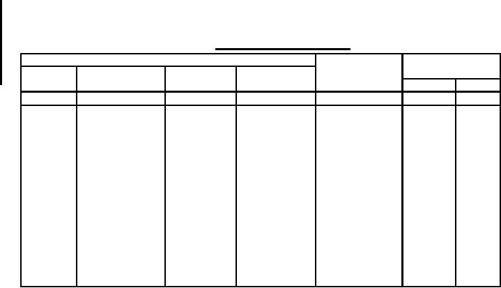
TABLE I. PIN designation identification.
PIN designation
Maximum cold
Lead diameter
Maximum
resistance
Style
Characteristic
voltage
Current rating
inches
mm
(±.002)
(±.05)
(volts)
(amperes)
(ohms)
FM10
A
125V
1/16A
9.10
.025
.64
FM10
A
125V
1/8A
2.700
.025
.64
FM10
A
125V
1/4A
.960
.025
.64
FM10
A
125V
3/8A
.560
.025
.64
FM10
A
125V
1/2A
.365
.025
.64
FM10
A
125V
3/4A
.215
.025
.64
FM10
A
125V
1A
.165
.025
.64
FM10
A
125V
1-1/2A
.105
.025
.64
FM10
A
125V
2A
.072
.025
.64
FM10
A
125V
3A
.047
.025
.64
FM10
A
125V
4A
.029
.025
.64
FM10
A
125V
5A
.019
.025
.64
FM10
A
125V
7A
.013
.025
.64
FM10
A
125V
10A
.008
.025
.64
FM10
A
32V
15A
.0053
.032
.82
3
For Parts Inquires call Parts Hangar, Inc (727) 493-0744
© Copyright 2015 Integrated Publishing, Inc.
A Service Disabled Veteran Owned Small Business