MIL-PRF-23419/12E
MIL-PRF-
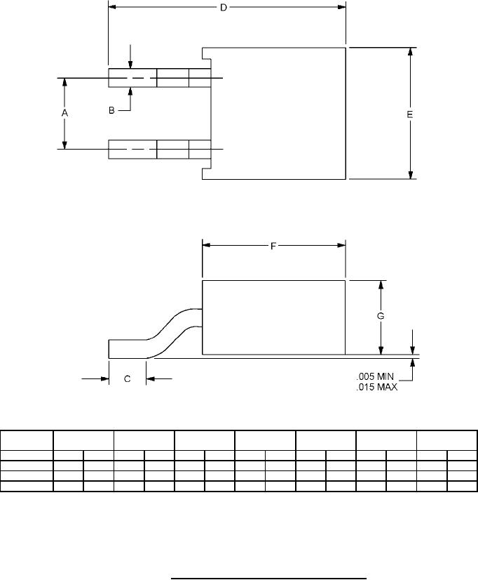
A
B
C
D
E
F
G
23419/12
Figure
Min.
Max.
Min.
Max.
Min.
Max.
Min.
Max.
Min.
Max.
Min.
Max.
Min.
Max.
1
.145
.175
.024
.028
.120
.135
.480
.540
.260
.280
.255
.275
.130
.145
2
.190
.210
.049
.054
.120
.135
.610
.685
.360
.380
.395
.410
.190
.210
3
.190
.210
.063
.067
.120
.135
.610
.685
.360
.380
.395
.410
.190
.210
NOTES:
1. Dimensions are in inches.
2. The figures referenced indicate figure 1, 2, and 3 of the straight lead fuse.
3. "F" option fuses will be supplied with solder coated leads. Solder coating shall extend up the
leads to a point between the fuse stand-off and the lead egress point.
FIGURE 4. Style FM12 fuse ("F" option formed leads).
4
For Parts Inquires call Parts Hangar, Inc (727) 493-0744
© Copyright 2015 Integrated Publishing, Inc.
A Service Disabled Veteran Owned Small Business