MIL-DTL-24646B
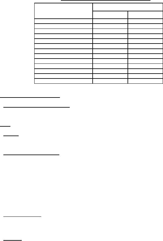
TABLE IV. Group A and Group B, zero defect sampling plan.
Sample size
Lot Size
Group A
Group B
1
to
8
All
3
9
to
25
8
3
26
to
50
8
5
51
to
90
8
6
91
to
150
12
7
151
to
280
19
10
281
to
500
21
11
501
to
1,200
27
15
1,201
to
3,200
35
18
3,201
to
10,000
38
22
10,001
to
35,000
46
29
35,001
to
150,000
56
29
150,001
and
over
64
29
4.5 Methods of examination and test.
4.5.1 Visual and dimensional examination. Fuse boxes shall be visually examined to verify that the materials,
design, construction, physical dimensions, marking, and workmanship are as specified in the applicable requirements
4.6 Tests.
4.6.1 Pull-test. A force of 20 pounds shall be applied to each fuse clip for a period of 5 to 10 seconds. The force
applied shall consist of a direct axial pull. Any sign of loosening of the clip or distortion or breaking of materials
surrounding the clip shall be cause for rejection.
4.6.2 Dielectric withstanding voltage. Fuse boxes shall be subjected to a dielectric withstanding voltage test as
specified in method 301 of MIL-STD-202. The following details shall apply:
a.
Test voltage: For circuits rated 600 volts (V) or less, twice rated circuit voltage plus 1,000 V; for circuits
rated above 600 V, 2.25 times rated voltage plus 2,000 V.
b.
Nature of potential: AC (root mean square (rms)).
c.
Points of application: Between electrical circuits and ground (enclosure). Where switches are present, they
shall be in the energized (closed) position.
d.
Rejection criteria: Failure to conform to 3.6.1.
4.6.3 Insulation resistance. Insulation resistance shall be measured as specified in method 302, test condition B of
MIL-STD-202. The test voltage shall be applied, between electrical circuits and ground (enclosure). When switches
are present, they shall be in the energized (closed) position. A resistance of less than 10 megohm shall be cause for
rejection.
4.6.4 Operation. Electrical circuits shall be energized at rated voltage and the voltage at the output circuits shall
be measured. When switches are installed, they shall be operated through all positions. Failure of the circuits to
function as specified in the wiring diagram or mechanical binding of the switches, where applicable, shall be cause for
rejection.
12
For Parts Inquires call Parts Hangar, Inc (727) 493-0744
© Copyright 2015 Integrated Publishing, Inc.
A Service Disabled Veteran Owned Small Business